20. CAST operation procedures Appendix
This appendix provides some guidance about typical operations necessary during maintenance or installation of the detector, vacuum system and water cooling at CAST. The majority of this appendix was written as an overview of the Septemboard operation at CAST, as required by CERN at the time.
We first quickly look at the terminology to describe different areas in the CAST hall in sec. 20.1. Then we go over the different systems. Detector high voltage (sec. 20.2), vacuum system (sec. 20.3), water cooling and gas supply (sec. 20.4) and the safety interlock systems (sec. 20.5).
We finally end with the CAST log files in sec. 20.6. These are the most important aspect in terms of performing data analysis with the data taken at CAST (magnetic field, solar tracking and more).
20.1. CAST terminology
In the CAST collaboration there is a common terminology in use to describe different parts of the hall / different bores and detector installations. Essentially, the two magnet bores and areas 'behind' them (seen from the center of the magnet if you will) are named by their being closest to either the Geneva airport and by the Jura mountains on the other side.
The magnet ends are named by whether a detector installed on that side observes the sunrise or the sunset. See fig. 1 for a schematic.

20.2. High voltage supply
The high voltage supply is an iseg HV module, which is located in the VME crate on the airport side of the magnet. The HV is controlled via a USB connection to the VME crate, which it shares with the FADC. The veto scintillator however has its own HV supply, since it needs a positive HV, instead of a negative one.
The detector uses \(\num{7}\) different high voltages. \(\num{5}\) of these are for the detector itself, \(\num{1}\) for the SiPM and the last for the veto scintillator on top. Their voltages are shown in tab. 30. The voltages actually used are defined in ./../TOS/config/HFM_settings.ini.
| Description | Channel | Voltage / V | TripCurrent / mA |
|---|---|---|---|
| grid | 0 | -300 | 0.050 |
| anode | 1 | -375 | 0.050 |
| cathode | 2 | -1875 | 0.050 |
| ring 1 | 3 | -415 | 0.100 |
| ring 29 | 4 | -1830 | 0.100 |
| veto scinti | 5 | +1200 | 2 |
| SiPM | 6 | -65.6 | 0.05 |
The HV cables in use are red cables with LEMO HV connectors. They run from the detector to an iseg HV module sitting in a VME crate on the airport side of the magnet. The cables are marked with zip ties and the same names as in tab. 30.
The interlock system for the high voltage supply is detailed in section 20.5.1, together with the other interlock systems in place.
20.2.1. Ramping the HV
The high voltage supply can be controlled in two different ways. Besides differing in usability terms (one is manual, the other automatic), the main difference between the two is the HV interlock, which is only partially usable in case of the manual HV control.
- in the manual way using the Linux software supplied by iseg. On the InGrid-DAQ computer it is located in ./../../ingrid/src/isegControl/isegControl. Depending on the setup of the machine, the software may need superuser rights to access the USB connection. With the software the given channel as shown in tab. 30 can be set up and the HV can be ramped up. Note: one needs to activate SetKillEnable such that the HV is shut down in case of a current trip (exceeding of specified current). One should then set 'groups' of different channels, so that grid, anode and ring 1 are shut down at the same time, in case of a current trip, as well as ring 29 and the cathode! In addition the trip current needs to be manually set about a factor 5 higher during ramping, because of capacitors, which need to be charged first. Otherwise the channels trip immediately. In this case the HV interlock is restricted to basic current restrictions. Anything detector related is not included!
in the automatic way via the TOS. The TOS takes care of everything mentioned above. To use the TOS for the HV control (and thus also use the complete HV interlock, as it exists at the moment), perform the following steps:
- check ./../TOS/config/HFM_settings.ini and compare with tab. 30 whether settings seem reasonable
after starting TOS and setting up the chips, call
> ActivateHFM
which will set up TOS to use the combined HV and FADC (due to both inside the same VME crate, they are intertwined). This configures the FADC and reads the desired HV settings, but does not set the HV settings on the module yet.
to write the HV to the HV module, call
> InitHV
which will write the HV settings from
HFM_settings.inito the HV module. At the end it will ask the user, whether the HV should be ramped up:Do you wish to ramp up the channels now? (Y / n)
If yes, the ramping progress will be shown via calls to the CheckModuleIsRamping() function (which can also be called manually in TOS).
This should properly ramp up all channels. It is possible that TOS fails to connect to the VME crate and hence is not able to ramp up the channels. The most likely reason for this is that the isegControl software is still open, since only one application can access a single USB interface at the same time.
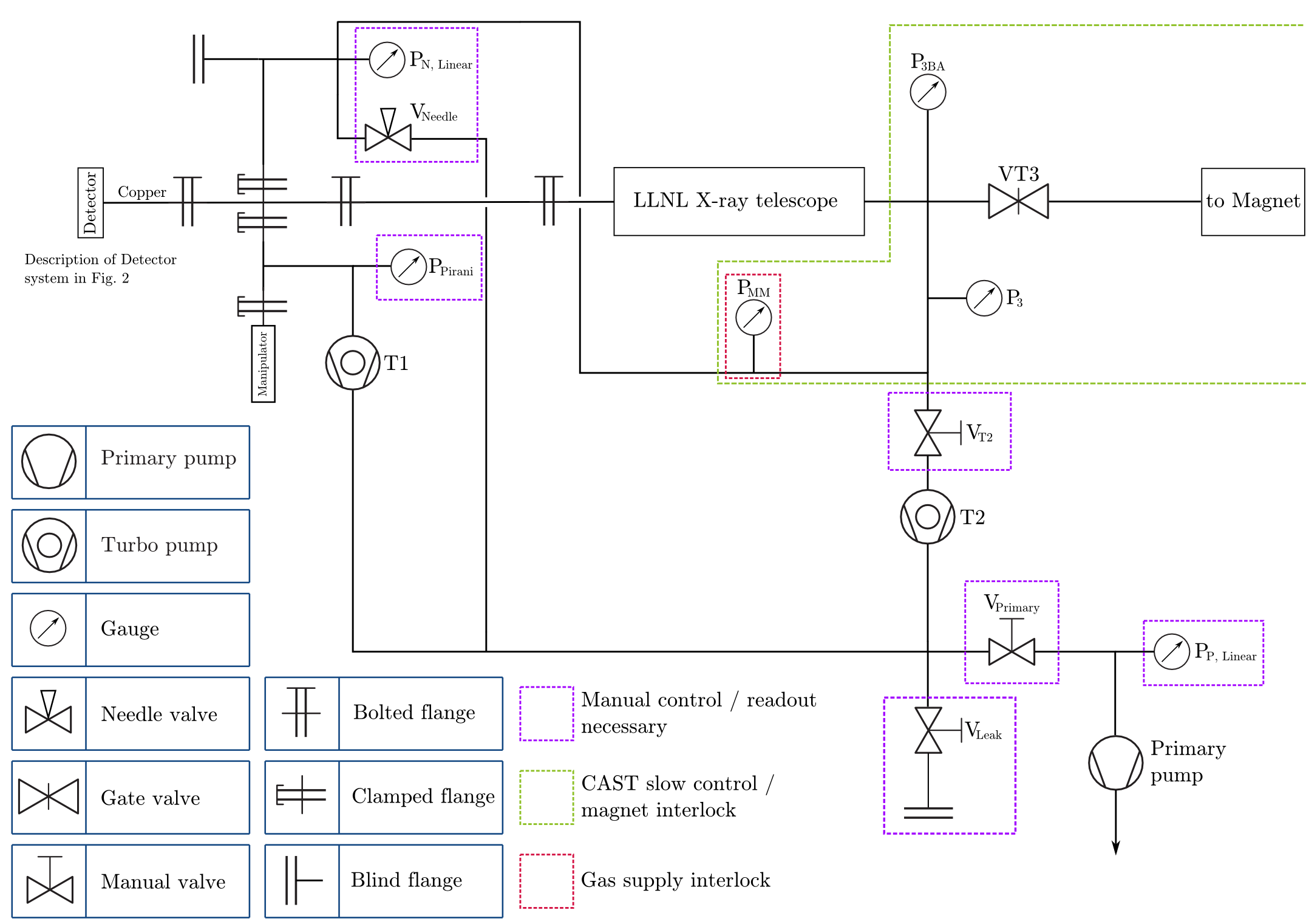
20.3. Vacuum system
This section covers the vacuum system of the detector. It is pumped via a single primary membrane pump and two turbo pumps. One turbo pump is used to pump the main vacuum vessel of the beam pipe, while the second small turbo pump is used to pump the interstage part of our X-ray source manipulator to reduce leakage during movement of the source.
Fig. 2 shows a schematic of the whole vacuum system including all interlock systems and the pressure sensors. The pressures of the sensors P3 and P-MM are used as an interlock for VT3 and the gas supply, respectively.
20.3.1. Vacuum operations
The vacuum system as described in sec. 20.3 usually does not require manual intervention during normal operation.
For maintenance the following two sections describe how to pump the system safely as well as how to flush it with nitrogen. Both processes are rather delicate due to the sensitive \(\ce{Si_x N_y}\) window. Pumping needs to be done slowly, \(O(\SI{1}{\milli\bar \per \second})\). To be able to do this, the needle valve \(V_{\text{Needle}}\) (cf. fig. 2) is installed. One may separate the vacuum volume into two separate vacua. A bad vacuum before the primary pump and after the turbo pumps T1 and T2 and a good vacuum before the turbo pump T2. There are three connections from the good vacuum to the bad one.
- through T2, closable via \(V_{\text{T2}}\), \(\SI{40}{\mm}\) tubing
- through the needle valve \(V_{\text{needle}}\), \(\SI{16}{\mm}\) tubing
- through T1 via the manipulator interstage, normally closed (see the note below), \(\SI{25}{\mm}\) tubing
3 is mainly irrelevant for pumping purposes, since there is no valve to open or close; it is always closed by a 2-O-ring seal to the good vacuum. While 1 is the main path for pumping during operation, it is 2 which is used during a pumping down or flushing of the system, since it can be controlled very granularly.
For both explanations below, it is very important to always think about each step (are the correct valves open / closed? etc.). A small mistake can lead to severe damage of the hardware (turbo pumps can break, the window can rupture).
Note: There is a third very small vacuum volume before T1, which is the volume up to the manipulator interstage. This volume is separate from the main good vacuum chamber, due to a 2-O-ring seal on both ends of the manipulator. Compare with fig. 2 at the location of the two clamped flanges 'above' the manipulator. One 2-O-ring seal is at the upper flange and one at the lower. This is because the manipulator part furthest from the beampipe is under air. In order to seal the air and the vacuum especially during movement of the source, these seals are in place. However, while the 2-O-ring seals provide decent sealing, it is not perfect. This is why the small turbo pump T1 is in place at all, to reduce the amount of air, which might enter the system during source manipulation. Another aspect to keep in mind is potential air, which can get trapped in between the two O-rings. This air will be released during movement of the seals. Especially after the system was open to air, it is expected that a small pressure increase on \(P_{\text{MM}}\) can be seen during operation, despite T1 being in place. After several movement cycles, \(O(10)\), these peaks should be negligible.
20.3.1.1. Pumping the vacuum
Before pumping it is a good idea to connect two linear gauges to the two \(P_{\text{Linear}}\) pressure sensors. To pump the system safely, perform the following steps:
- Make sure every pump is turned off.
- Make sure every valve in the system is closed:
- \(V_{\text{Primary}}\)
- \(V_{\text{Leak}}\)
- \(V_{\text{T2}}\)
- \(V_{\text{Needle}}\)
- Connect a linear gauge to \(P_{\text{P, Linear}}\) on the primary pump line.
- Start the primary pump. Tubing up to \(V_{\text{Primary}}\) will be pumped, visible on linear gauge connected to \(P_{\text{P, Linear}}\). Check that the second linear gauge remains unchanged, if not \(V_{\text{Primary}}\) and \(V_{\text{Needle}}\) is open!
- Once \(P_{\text{P, Linear}}\) shows \(\leq \SI{10}{\milli bar}\), slowly open \(V_{\text{Primary}}\), again checking \(P_{\text{N, Linear}}\) remains unchanged. This will increase the pressure on \(P_{\text{P, Linear}}\) again until the volume is pumped.
- This step is the most crucial. With \(V_{\text{T2}}\) still closed,
very carefully open \(V_{\text{Needle}}\), while keeping an eye on
\(P_{\text{N, Linear}}\). Note that \(V_{\text{Needle}}\) has two
locking mechanisms. The knob at the end with the analog indicator
and a general lock in front of that. While the analog indicator
shows
000, open the general lock. Then slowly start turning the knob. At around300the pressure on \(P_{\text{N, Linear}}\) should slowly start to decrease. Keep turning the knob until you reach a pump rate of \(O(\SI{1}{\milli \bar \per \second})\). You will have to keep opening the needle valve further, the lower the pressure is to keep the pump rate constant. - Once both linear gauges have equalized (up to different offsets), close the needle valve again.
- Open \(V_{\text{T2}}\).
- Start T2 by turning on the power and pressing the right most button. Use the arrow buttons to select the 'actual RPM' setting to see that the turbo is spinning up. Final speed should be set to \(\SI{1500}{\Hz}\).
- While T2 is spinning up, start T1 by turning on the power at the back. There is no additional button to be pressed.
The system should now be in the following state:
- \(V_{\text{Leak}}\) closed
- \(V_{\text{Needle}}\) closed
- \(V_{\text{T2}}\) open
- \(V_{\text{Primary}}\) open
- T2 & T1 running
- Primary pump running
If so, the system is now pumping. Note that it may take several days to reach a vacuum good enough to satisfy the interlock.
20.3.1.2. Flushing the system
Flushing the system is somewhat of a reverse of pumping the system. Follow these steps to safely flush the system with nitrogen. See section 20.4.4 for an explanation of which valves need to be operated to open the nitrogen line. Before flushing the system connect two linear gauges to both \(P_{\text{Linear}}\) sensors.
- Make sure the turbo pumps are turned off, if not yet turn both off and wait for them to have come to a halt.
- Turn off the primary pump.
- Close \(V_{\text{T2}}\). \(V_{\text{Leak}}\) and \(V_{\text{Needle}}\) should already be closed, while \(V_{\text{T2}}\) and \(V_{\text{Primary}}\) should still be open.
- Connect the nitrogen line to the blind flange before \(V_{\text{Leak}}\).
- Slowly open \(V_{\text{Leak}}\), while checking both linear gauges. Make sure only the pressure on \(P_{\text{P, Linear}}\) increases, while \(P_{\text{N, Linear}}\) remains under vacuum. If not, another valve is still open. Close \(V_{\text{Leak}}\) immediately again!
- Keep flushing nitrogen, until \(P_{\text{P, Linear}}\) gets close to \(\SI{1000}{\milli\bar}\) (the sensors will never actually reach that value).
- Close \(V_{\text{Leak}}\) again to make sure you do not put the system over one atmosphere of pressure.
- This step is the most crucial. With \(V_{\text{T2}}\) still closed,
very carefully open \(V_{\text{Needle}}\), while keeping an eye on
\(P_{\text{N, Linear}}\). Note that \(V_{\text{Needle}}\) has two
locking mechanisms. The knob at the end with the analog indicator
and a general lock in front of that. While the analog indicator
shows
000, open the general lock. Then slowly start turning the knob. At around300the pressure on \(P_{\text{N, Linear}}\) should slowly start to increase. Keep turning the knob until you reach a pump rate of \(O(\SI{1}{\milli \bar \per \second})\). - You will notice that the pressure on \(P_{\text{P, Linear}}\) will start to decrease, since the air will distribute in a larger volume. Open \(V_{\text{Leak}}\) again slightly to keep \(P_{\text{P, Linear}}\) roughly constant.
- Keep flushing with \(\SI{1}{\milli\bar\per\second}\) until both sensors read \(O(\SI{1000}{\milli\bar})\).
- Close all valves in the system again.
This way the system is safely flushed with nitrogen. This helps to pump faster after a short maintenance, because less humidity can enter the system.
20.4. Watercooling system & gas supply
In this section the watercooling system as well as the gas supply is discussed. In section 20.4.3 a combined schematic of both systems is shown.
20.4.1. Watercooling
In order to keep the detector cool enough to avoid noise and damage to the septemboard, a watercooling system is used. This section describes the relevant information for the system as used at CAST.
To readout the temperature two PT1000 temperature sensors are installed on the detector. One is located on the bottomside of the intermediate board (outside of the detector volume), while the other is located on the bottom side of the Septemboard. This temperature \(T_{\text{Septem}}\) is also included in the schematic 6 below, because it was intended to be part of the HV interlock, as described in 20.5.1. In the end it was not due to lack of time for proper testing. 1
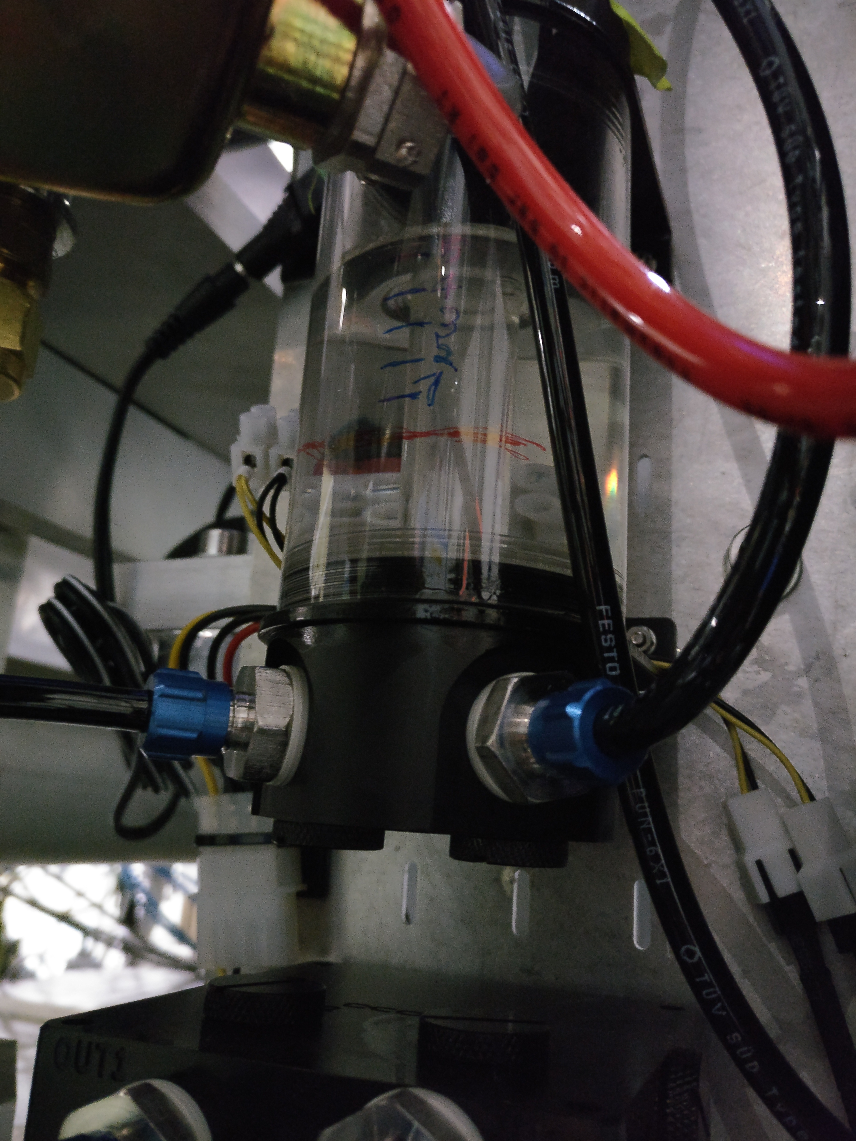
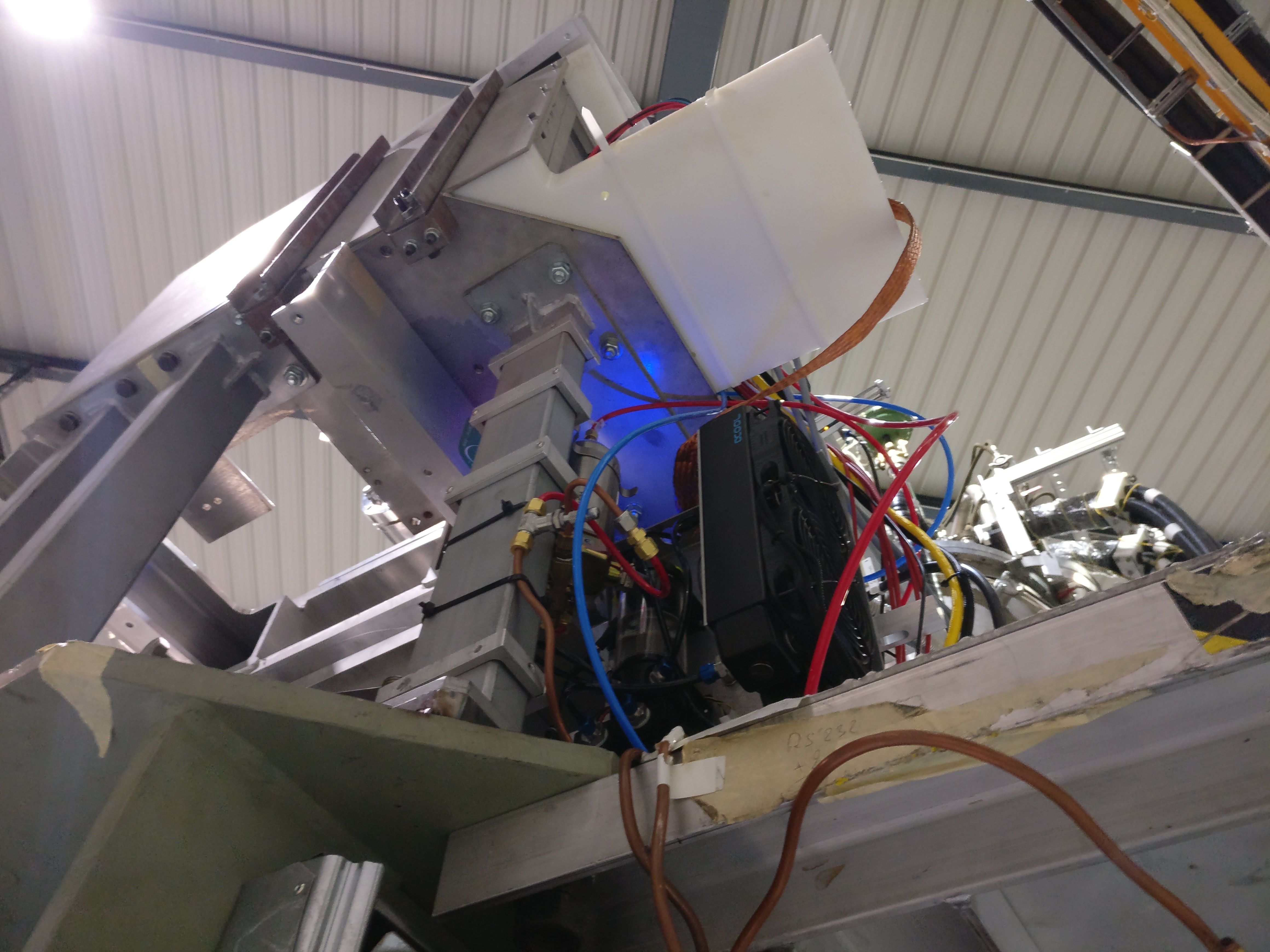
Fig. 3(b) shows the main part of the system including the pump, reservoir and radiator. The tubing is specifically chosen in blue to clear up potential confusion with other tubes used in the detector system. 2 These tubes use special Festo quick couplings, which cannot be connected to the connectors of the gas supply, to avoid potential accidents. The tubes have zipties installed on them, which label the tubes as well, with the naming convention as it is used in fig. 6.
- Maintenance
- At the end of every shift it should be checked, whether the water level in the reservoir is still above the red line seen in Fig. 3(a). If not, water should be added by the shift coordinator (or trusted shifters).
20.4.2. Gas supply
The gas supply uses red tubing (in parts where flexible tubing is used) to differentiate itself from the watercooling system. Additionally, the tubes have zipties showing which tube is which. These are located on both ends of the tubes. The naming convention is the same as in 6. The connectors of the gas line are standard Swagelok connectors.
As can be seen in the schematic, the gas supply has 4 valves on the inlet side and 2 on the outlet side. In addition a buffer gas volume is installed before the detector for better flow control.
It follows a short explanation of the different valves:
- \(V_{\text{in, 1}}\) is the main electrovalve installed right after the gas bottle outside the CAST hall.
- \(V_{\text{interlock}}\) is installed is the electrovalve installed below the platform where the beamline is located. This valve is part of the gas supply interlock, as described in section 20.5.2.
- \(V_{\text{in, 2}}\) is the manual valve located on the second gas supply mounting below the beamline.
- \(V_{\text{in, N1}}\) is the first needle valve, which is located on the second gas supply mounting below the beamline. It is the one part of the flow meter placed there.
- \(V_{\text{P}}\) is the valve inside the pressure controller, which is placed roughly below the telescope (on the platform), while \(P_{\text{Detector}}\) is the pressure gauge inside this controller.
20.4.2.1. Gas system operations
If the requirements of the gas supply interlock are satisfied (cf. sec. 20.5.2), it is possible to flush the detector with gas. For that, follow these steps:
- Make sure the pressure controller is connected and running. Check InGrid-PLC computer in control room and see if pressure control software is running. If gas supply is currently closed, reported pressure inside the detector is usually reported to \(\SIrange{960}{980}{\milli\bar}\).
- Outside the building, open the main valve of the currently active gas bottle (check the arrow on the bottle selector mechanism). See fig. 4(a).
- Open the second valve near the bottle.
- Pressure values should be:
- gas bottle: \(\sim\SIrange{30}{100}{\bar}\)
- pre-line pressure: \(\sim\SI{7}{\bar}\)
- line pressure: \(\sim\SI{0.45}{\bar}\)
- Activate the gas supply at the interlock box by turning the key to
Security onand pressing the large button. See fig. 4(b). - Go to the airport side of the magnet. Open the valve on the InGrid gas panel below the telescope platform. See fig. 5.
- Slowly open the needle valve on the flow meter on the previous panel. Increase gas flow up to \(\sim\SI{2}{\liter\per\hour}\).
- Open the needle valve on the gas supply line on the side of the platform.
- After \(\SIrange{5}{10}{\minute}\) the pressure controller on the InGrid-PLC computer should report \(\SI{1050}{\milli\bar}\).
Now the detector should be flushed with \(\ce{Ar} / \ce{iC_4H_{10}}\). Before turning on the HV, make sure to flush for at least \(\SI{12}{\hour}\) to be on the safe side.


20.4.3. Combined schematic (water & gas)
Fig. 6 shows a combined schematic of both the watercooling system and the gas supply. Additionally, the relevant interlock systems and their corresponding members are shown.

20.4.4. Nitrogen supply
Nitrogen is supplied by a nitrogen bottle outside the building. To open the nitrogen line, 5 valves need to be opened. The line ends in a copper pipe on the airport side, which is usually there rolled up (the copper is somewhat flexible).
- Open the lever on the nitrogen bottle outside the building (see fig. 7(a)).
- Open the valve next to the bottle.
- Go to the gas lines next to the control room. The right most line (see fig. 7(b) and fig. 8(a)) is the nitrogen line. Open the valve.
- Open the needle valve on the flow meter to the right of the previous valve.
- Open the needle valve on the airport side of the magnet.
This should be all to open the nitrogen line. The flow through the pipe is not too large, but it should be large enough to feel it on the back of the hand.


20.5. Interlock systems
This section describes the interlock systems, which are related to the detector. There are 3 interlock systems to speak of.
- The CAST magnet interlock, which prohibits the gate valve VT3 to be opened, if the pressure in the vacuum system is not good enough.
- A gas supply interlock, which makes sure the detector is only flushed with gas, if all other parameters are considered nominal (mainly a good vacuum in the system).
- A HV interlock, which makes sure the detector is only under HV, if the temperature of the detector is still good (otherwise a lot of sparks are produced) and the currents on the HV lines are nominal.
20.5.1. HV interlock
Note: This section describes the high voltage interlock as it was intended. But as mentioned multiple times previously it was deactivated for final data taking due to several bugs causing it do trigger under non intended circumstances.
The HV system is part of an interlock, which tracks the following properties:
- detector temperature
- currents on HV lines
- TO BE IMPLEMENTED: gas pressure inside the detector 3
The detector temperature is measured at two points by PT1000 sensors. One of these is located on the bottom side of the intermediate board (and thus is more a measure the the temperature surrounding the detector), while the second is located on the bottom side of the septemboard. The second is the best possible measure for the temperature of the InGrids. However, there is still a PCB separating the sensor from the actual InGrids. This means there is probably a temperature difference of a minimum of \(\SI{10}{\celsius}\) between the measured value and the actual temperature of the InGrids.
Whenever the TOS is configured to use the FADC readout and control the HV (note: the two are intertwined, since both sit in the same VME crate, which is controlled via a single USB connection), a background process which monitors the temperature is started. If the temperature exceeds the following boundaries
\[ \SI{0}{\celsius} \leq T \leq \SI{60}{\celsius} \]
on the lower side of the septemboard, the HV is shut down immediately. The lower bound is of less practical value in a physical sense, but in case of sensor problems negative temperature values may be reported. As the upper bound a value is taken at which sparks and general noise seen on the pixels becomes noticeable.
The interlock currents at which the HV trips are already shown in tab. 30. During ramp up of the HV, these trip currents are set higher to avoid trips, while capacitors are being charged.
The gas pressure within the detector was intended to be included into the interlock system to shut down the HV if the pressure inside the detector leaves a certain safe boundary, since this could indicate a leak in the detector or an empty gas bottle.
20.5.2. Gas supply interlock
The gas supply is also part of an interlock system. In case of a window rupture the potential amount of gas that might enter the vacuum system should be limited by electrovalves. Ideally the pressure inside the detector had been included into the gas supply interlock. This could have made sure the gas inlet and outlet are closed in case the pressure inside the detector drops (which might indicate a leak somewhere or an empty gas bottle) or in case of rising pressure.
The latter is not as important though, because a pressure controller is already installed behind the detector, which controls the flow such that the pressure stays at \(\SI{1050}{\milli \bar}\). While a failure of the controller is thinkable, potentially leading to a pressure increase inside the detector, it is questionable whether this could be dealt with using this interlock system. That is because the pressure sensor used is part of the pressure controller.
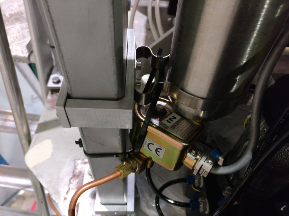
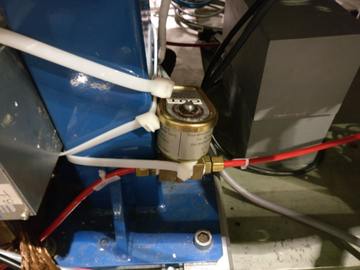
Three electrovalves are placed on the gas line of the detector. One, \(V_{\text{in}}\), is outside of the building next to the gas bottles (see fig. 9(a)). The second valve \(V_{\text{interlock}}\) is located right before the buffer volume, next to the watercooling system, below the shielding platform, fig. 9(b). The final electrovalve \(V_{\text{out}}\) is located after the pressure controller on a blue beam, which supports the optical table below the telescope (see fig. 9(c)). These valves are normally closed, i.e. in case of power loss they automatically close. They are open if a voltage is applied to them.
The valves are connected to the pressure sensor \(P_{\text{MM}}\) (see fig. 2). The pressures to activate the interlock system is defined by upper and lower thresholds asymmetrically. They are as follows:
\begin{align*} P_{\text{MM, Gas enable}} \leq \SI{9.9e-3}{\milli \bar} \end{align*}and
\begin{align*} P_{\text{MM, Gas disable}} \leq \SI{2e-2}{\milli \bar} \end{align*}
20.5.2.1. Note on pressures of interlock extended
It's possible the exact numbers are slightly wrong. At this point I'm not certain anymore, but I had a note to cross check them in the document the above was initially in (a document about the detector & operation for CERN).
20.5.3. CAST magnet interlock
The main CAST magnet interlock, as it is relevant to our detector, is as follows. The gate valve VT3 separating the magnet volume from the telescope volume is interlocked. Only if the vacuum in the telescope volume is good enough, VT3 can be opened while the interlock is activated.
For this the pressure of \(P_{\text{3}}\) is considered relevant (cmp. fig. 2). The upper and lower thresholds which activate and deactivate the interlock are asymmetric and as follows:
\begin{align*} P_{\text{3, VT3 enable}} &\leq \SI{1e-5}{\milli\bar} \end{align*}while
\begin{align*} P_{\text{3, VT3 disable}} &\leq \SI{8e-5}{\milli\bar}. \end{align*}This is to make sure there can be no rapid toggling between the two states during pumping or flushing the system.
20.6. CAST log files
The CAST experiment is controlled by a central computer running a slow control system written in LabVIEW 4. It receives data from all sensors installed at CAST (vacuum pressures, temperatures, magnet current, magnet position and so on). A separate LabVIEW program is responsible for controlling the magnet position, either by moving the magnet to a specific coordinate or by following the Sun, if it is in reach of the magnet.
The slow control software records all sensor data and presents it in a multitude of graphs. All data is also written to log files. There are two different kinds of log files of interest in the context of the septemboard detector at CAST.
- The general slow control log file is a versioned space separated
values file (similar to a comma separated value (CSV) or tab
separated value (TSV) file, except using spaces as delimiters). The
filename contains the version number, which decides the columns
contained in the file and their order. A
Version.idxfile maps version numbers to file columns for easy access. These slow control log files normally contain one entry every minute. For the Septemboard detector of interest in this file are mainly the magnet current, relevant vacuum pressure sensors and the state of the gate valveVT3. - The second kind of log files are the tracking log files. These are also space separated value files with fields describing the pointing location of the magnet as well as whether the magnet is currently tracking the Sun.
Both of these log files need to be read by the analysis software to decide whether one or multiple trackings took place in a given background run and if so extract the exact start and end time for a precise data splitting and calculation of background / solar tracking time.
Generally the latter log files are all that is needed to determine the existence of a solar tracking. However, the slow control log file can be used as a further sanity check to make sure the gate valve was actually open and the magnet under current during the solar tracking.
This is implemented in the cast_log_reader program part of
TimepixAanlysis. See sec. 34.3.11 for
more details on the program.
20.6.1. Add tracking log information to background files extended
The code dealing with the log files is ./../CastData/ExternCode/TimepixAnalysis/LogReader/cast_log_reader.nim
In case previous log information is available we first have to remove that information. This is done by just calling the program just with the H5 file as an input:
cast_log_reader h5file -f ~/CastData/data/DataRuns2017_Reco.h5
cast_log_reader h5file -f ~/CastData/data/DataRuns2018_Reco.h5
With an 'empty' (in terms of tracking information) HDF5 file we can then go ahead and add all tracking information to them. This of course requires the tracking log files:
./cast_log_reader tracking -p ../resources/LogFiles/tracking-logs --h5out ~/CastData/data/DataRuns2017_Reco.h5
./cast_log_reader tracking -p ../resources/LogFiles/tracking-logs --h5out ~/CastData/data/DataRuns2018_Reco.h5
One can also run it without any output H5 file --h5out to simply get
information about the runs. In particular all runs
./cast_log_reader tracking -p ../resources/LogFiles/tracking-logs --startTime 2017/09/01 --endTime 2018/12/30
FILTERING TO DATE: 2017-09-01T02:00:00+02:00 and 2018-12-30T01:00:00+01:00 There are 120 solar trackings found in the log file directory The total time of all trackings: 186 h (exact: 1 week, 18 hours, 46 minutes, and 19 seconds) Total time the magnet was on (> 1 T): 0 h h
This lists 5 runs that were not part of our data taking, meaning we lost them.
And finally (and most useful for information purposes) we can run the log reader over the files and do a fake insert (aka dry run) of inserting the files, which only outputs the run information including which runs were missed:
./cast_log_reader tracking -p ../resources/LogFiles/tracking-logs \
                  --startTime 2017/09/01 --endTime 2018/05/01 \
                  --h5out ~/CastData/data/DataRuns2017_Reco.h5 --dryRun
There are 70 solar trackings found in the log file directory
The total time of all trackings: 109 h (exact: 4 days, 13 hours, 3 minutes, and 22 seconds)
Total time the magnet was on (> 1 T): 0 h h
Filtering tracking logs to date: 2017-09-01T02:00:00+02:00 and 2018-05-01T02:00:00+02:00
======== Logs mapped to trackings in the output file: ========
for run: 76
for run: 77
for run: 78
for run: 79
for run: 80
for run: 81
for run: 82
for run: 82
for run: 84
for run: 86
for run: 87
for run: 87
for run: 89
for run: 90
for run: 91
for run: 92
for run: 94
for run: 95
for run: 97
for run: 98
for run: 99
for run: 100
for run: 101
for run: 103
for run: 104
for run: 106
for run: 105
for run: 107
for run: 109
for run: 112
for run: 112
for run: 114
for run: 113
for run: 115
for run: 117
for run: 119
for run: 121
for run: 123
for run: 124
for run: 124
for run: 125
for run: 127
for run: 146
for run: 150
for run: 148
for run: 152
for run: 154
for run: 156
for run: 158
for run: 160
for run: 162
for run: 162
for run: 162
for run: 164
for run: 164
for run: 166
for run: 170
for run: 172
for run: 174
for run: 176
for run: 178
for run: 178
for run: 178
for run: 178
for run: 178
for run: 180
for run: 182
for run: 182
================================================================
======== Logs not mapped to a run ==========================
================================================================
And for 2018:
./cast_log_reader tracking -p ../resources/LogFiles/tracking-logs \
                  --startTime 2018/05/01 --endTime 2018/12/31 \
                  --h5out ~/CastData/data/DataRuns2018_Reco.h5 --dryRun
There are 50 solar trackings found in the log file directory
The total time of all trackings: 77 h (exact: 3 days, 5 hours, 42 minutes, and 57 seconds)
Total time the magnet was on (> 1 T): 0 h h
Filtering tracking logs to date: 2018-05-01T02:00:00+02:00 and 2018-12-31T01:00:00+01:00
======== Logs mapped to trackings in the output file: ========
for run: 240
for run: 242
for run: 244
for run: 246
for run: 248
for run: 250
for run: 254
for run: 256
for run: 258
for run: 261
for run: 261
for run: 261
for run: 263
for run: 265
for run: 268
for run: 270
for run: 270
for run: 272
for run: 272
for run: 272
for run: 274
for run: 274
for run: 274
for run: 276
for run: 276
for run: 279
for run: 279
for run: 281
for run: 283
for run: 283
for run: 283
for run: 285
for run: 285
for run: 287
for run: 289
for run: 291
for run: 291
for run: 293
for run: 295
for run: 297
for run: 297
for run: 298
for run: 299
for run: 301
for run: 301
for run: 303
for run: 306
================================================================
======== Logs not mapped to a run ==========================
================================================================
Footnotes:
As mentioned in a previous footnote, the decision to take it out of the HV interlock is the reason for loss of temperature logging data.
This change was made after the 'window accident'.
The gas pressure inside the detector was intended to be added to the HV interlock as well, but also due to lack of time it never was.